Overview
In this project we learn about several methods of manipulating geometry meshes. We are introduced to Bezier curves and surfaces and a process for generating them through de Casteljau's algorithm. We also are introduced to the halfedge data structure, a linked-list variant that is able to encode mesh geometry such as vertices, faces, and edges, and traverse among the mesh through the half-edge.
It appears that we've learned how to perform the smoothing operation in software such as Autodesk Maya, through the use of de Casteljau's to generate Bezier surfaces. This also explains the reasoning behind "beveling," leaving edges closer together in order to retain more of the original shape after smoothing, because there is less distance to interpolate between. I believe the graph editor also uses a Bezier curve to interpolate between animation keyframes, which is why an animation with keyframes too far spaced apart looks robotic and unnatural - the computer simply generates a smooth curve through interpolating between points.
I'm wondering if the halfedge structure is why there is an insistence on using quadrilaterals in modeling software. Perhaps it is because half-edge splits and flips seem to require at least four sides to work with. Therefore, at least a quadrilateral (two triangles) is required for the data structure to work best. I would also guess that loop subdivision is a process used in real-time media such as game engines. As far as I know, some engines do not allow smooth models, so the appeareance of smoothness must be approximated in some fashion. Up-sampling could certainly generate a smoother display without compromising the mesh's original appeareance, although of course it would probably be more expensive to render due to higher polygon count.
Section I: Bezier Curves and Surfaces
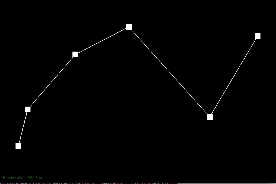
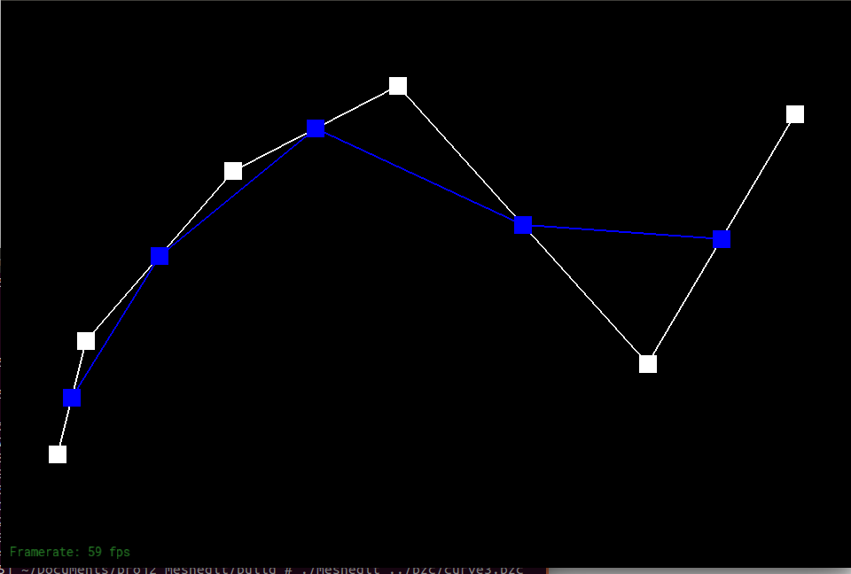
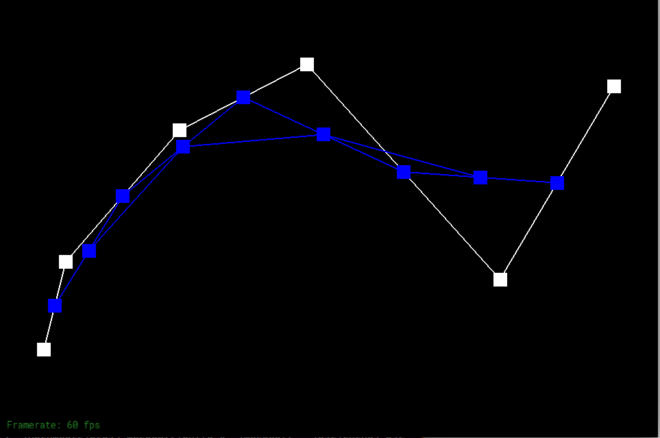
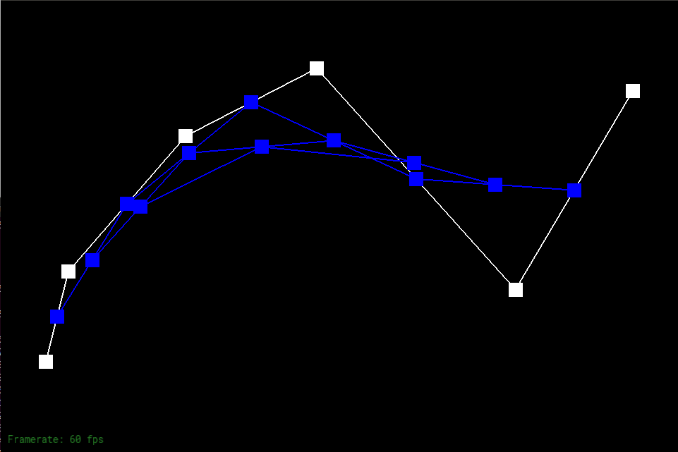
Part 1: Bezier curves with 1D de Casteljau subdivision
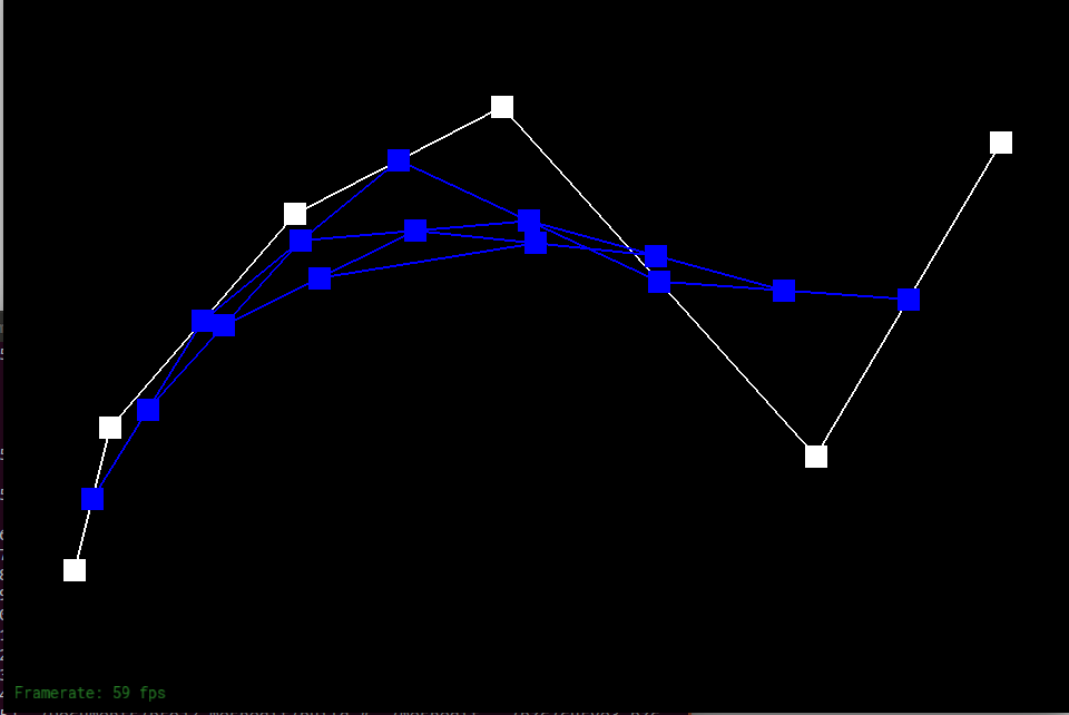
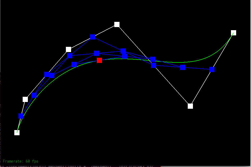
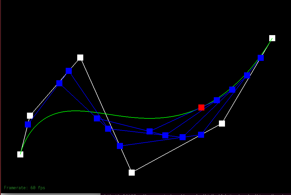
Bezier curves are a mathematical way of generating smooth curves between points. To implement this, we use what is known as "de Casteljau's algorithm." The algorithm works by continually interpolating between consecutive points until only one point remains. This is illustrated in the pictures below: at each step of the evaluation, a new control point is created that is interpolated from two consecutive points using a value t that is between 0 and 1. This process repeats for every consecutive pair until there is only one point left, which is the final point on the Bezier curve. To generate the entire curve, we run de Casteljau's for all t between 0 and 1.
|
|
|
|
|
|
|
|
Part 2: Bezier surfaces with separable 1D de Casteljau subdivision
De Casteljau's algorithm can also be applied to three-dimensional surfaces. It works in much the same way, but with a few extra steps to account for an additional dimension. Suppose groups of points like the pictures above exist in the xy-plane, and multiple sets are lined along the z axis. A 1D de Casteljau's is calculated for each group of points in the xy-plane. Then, for the resulting points, another de Casteljau's is calculated across just the z-axis (or whichever axis on which the points fall). This results in us getting a single 3D point. In order to generate the Bezier surface, we calculate the points for all u and v between 0 and 1, where u is the interpolation value for the xy-plane and v is the interpolation value along the z-axis.
Section II: Sampling
Part 3: Average normals for half-edge meshes
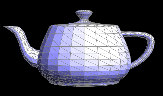
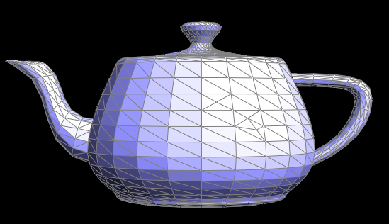
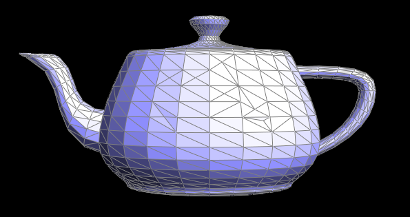
In this part of the project we implement area-weighted average normal vectors at each vertex. This process makes use of the halfedge, a data structure that allows us to encapsulate data about the mesh in what can be described as a linked-list variant. To retrieve the average normal vector, we make use of the halfedge to retrieve all neighboring vertices, take the sum of the cross products of all of the triangle edges, and finally normalize that sum.
|
|
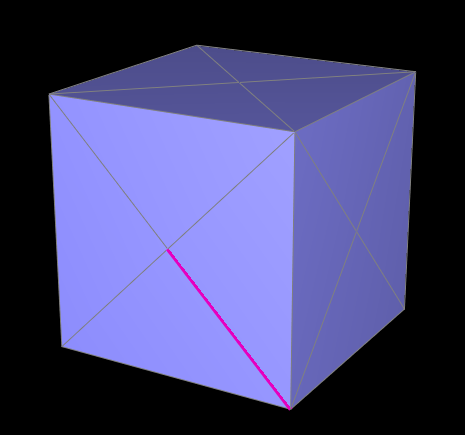
Part 4: Half-edge flip
The half-edge flip is a mesh operation that is exactly as it sounds: flipping an edge. You can visualize it as a a rhombus with one diagonal traced in. After flipping the edge, the traced line now is in the position of the other diagonal. To perform this operation with the halfedge data structure, you need to perform a sequence of pointer reassignments, making sure to reassign the halfedges and their properties, such as source vertex, and also reassign the halfedges that faces, vertices, and edges point to so as to be consistent with the new geometry. What I found helpful in this part was drawing a diagram of the mesh before and after a flip operation. By labeling all halfedges, vertices, faces, and edges, it is much easier to visualize the new properties of each mesh object and correctly reassign what needs to be changed.
|
|
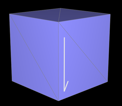
Part 5: Half-edge split
Half-edge split is fairly similar to half-edge flip, but now, instead of simply changing the diagonal that is filled in in the rhombus, we fill in both diagonals, resulting in an object with four faces. As in before, splitting halfedges consists of many pointer reassignments, but new halfedges, faces, edges, and one vertex must also be allocated. Also as in before, it was incredibly helpful to draw a picture and label each element in the new geometry. I also marked any new elements that I needed to create on the diagram.
|
|
|
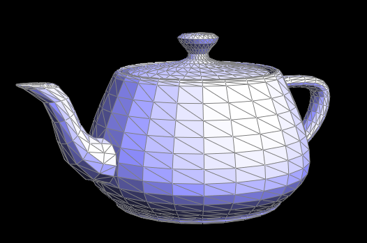
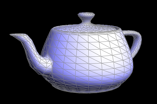
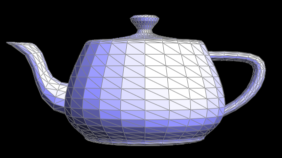
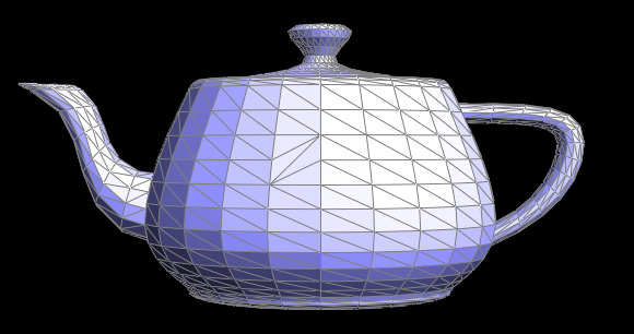
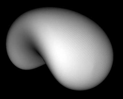
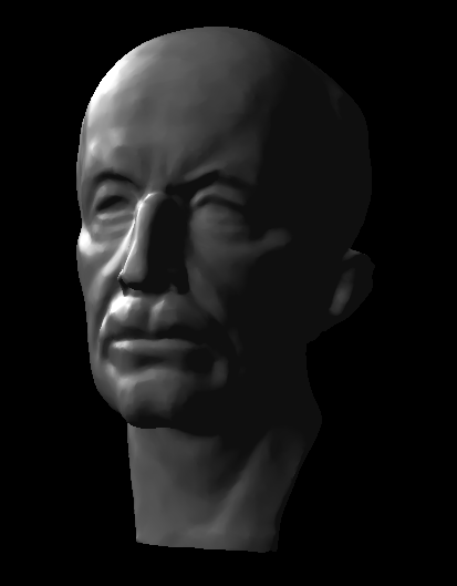
Part 6: Loop subdivision for mesh upsampling
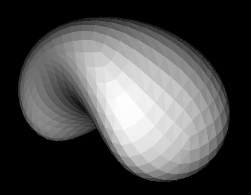
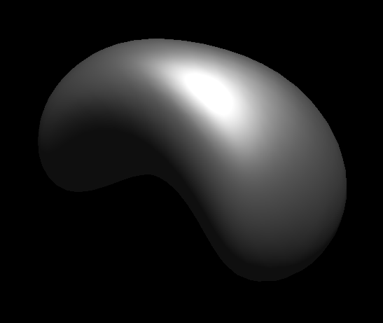
Loop subdivision consists of combining both halfedge splitting and flipping to "upsample" the mesh topology, that is, to improve the display or resolution of the mesh through an interpolation scheme. You can quite noticeably see the improvement in display quality of the bean mesh pictured below. While the mesh without up-sampling has rather noticeable polygon structure, the mesh after up-sampling twice appears far smoother, especially at a distance.
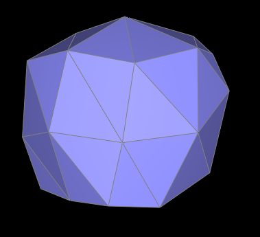
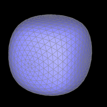
Sharp corners and edges become noticeably deformed after up-sampling, as the subdivision scheme attempts to interpolate between greater distances. You can see in the second row of pictures that the cube almost immediately becomes more rounded in shape after just one round of up-sampling. Initially, it becomes slightly asymmetric after repeated subdivisions, and this is a result of the cube not initially having symmetric geometry. Because each face is only composed of two triangles, the diagonal created by the boundary edge on a particular face did not always match the edge on its opposing face. To fix this, I simply split every face such that each face had an 'X' shape on them. This results in a rounded cube after several rounds of subdivision.
|
|
|
|
|
|
Section III: Shaders
Part 7: Fun with shaders
Finally, we implement Blinn-Phong shading through a very simple fragment shader. It consists of combining ambient, diffuse, and specular lighting vectors to simulate a reflective surface.
|
|
|
|